Laser Scanning Confocal Microscopy
1. What is Laser Scanning Confocal Microscopy?
The images observed under a general microscope have light coming from the focal plane and the out-of focal plane . Therefore, the image quality provided is poor in resolution and cannot be analyzed layer by layer. Samples were observed microscopically.
Laser scanning confocal microscopy uses an image formed by collecting light from the focal surface of the sample through an optical pinhole aperture, and excludes light from different focal surfaces outside the optical pinhole aperture to form a conjugate focus image removing the stray light from traditional microscope images can provide higher optical resolution and better axial and lateral analysis (point spread function) (Figure 1)
Through this technology, users can arbitrarily specify the upper and lower point positions of the sample according to the thickness of the sample, set the thickness of each optical section, and perform continuous optical tomography (Figure 2); finally, it can be reorganized into a three-dimensional Images (Figure 3), continuous 3D movie screening (Avi 1), and rotation or cross-section observation at various angles (Avi 2).
2. Composition of Laser Scanning Confocal Microscopy system
The Laser scanning confocal microscopy system is mainly composed of A. laser light source B. microscope C. confocal scanner D. computer E. application software.
A. Laser light source
The laser light source can provide extremely pure single wavelength (monochromatic), energy uniformity (high photon, energy), and the laser beam has a fixed phase (coherence). These characteristics allow the laser beam to be focused on a small point. Therefore, it can be effectively used as a light source for microscopy scanning.
Laser light sources include
a. Visible laser light source :
Including ion laser, helium-neon laser and diode laser
b. Ultraviolet laser light source :
Including helium-cadmium laser and hydrogen ion ultraviolet laser
c. Infrared laser light source :
Ti-sapphire Ultrafast laser
d. White light laser source :
Emit 440-790nm continuous band laser.
(For the laser light source equipped in this laboratory, please refer to "Our Facility")
B. Microscope
a. Most of the current confocal systems can be used on upright or inverted microscopes, and the scanner can be switched and assembled on both microscopes.
b. Provide higher and wider amplitude correction for UV and IR.
c. The optical lens uses a high-NA oil lens with high optical resolution, such as
PL-APO 40x/1.25 Oil, PL-APO 63x/1.32 Oil,
PL-APO 63x/1.40 Oil, PL-APO 100x/1.32,
PL-APO 100x/1.40
C. Confocal Scanner
a. The scanning sensing system uses high-resolution point-scanning. Basically, there are traditional filter-based systems and new generation spectral-based systems . The equipment of this laboratory belongs to the latter.
b. In the design of the filter system, the X-Y scanning mirror is mainly used to capture the X-Y coordinates of the sample, and the rise and fall of the Z-stage is used as the longitudinal scanning orientation of the Z-axis. Therefore, the X-Y-Z coordinates with the timing control (T), that is Can be used for various combination scanning applications, such as X-T, Y-T, XY, XY-T, XYZ, XYZ-T...etc.
c. The scanner's reflected fluorescence detection can use a CCD Camera or PMT (photomultiplier) as photon sensing; as for general transmitted light image capture, such as phase contrast, it is installed in the microscope. Detected by the penetrating light sensor.
d. The scanner equipped in this laboratory is a rotating K-scanner, which can provide ultra-high optical resolution and multi-dimensional scanning (nD: multi-dimentional scanning) at any scanning speed. Its resolution is Up to 8192 x 8192 x 8192 pixels.
D. Computer workstation
a. The computer system must be able to stably control all software and hardware.
b. Users should set up their own image processing workstation, use the conjugate focal system as the image acquisition center, and then transfer the results one-way to a personal computer for further editing and processing.
E. Application software
a. High-end and high-speed image processing software with user-friendly and easy operation is the development trend. At present, they are all developing towards the Windows 10 operating environment.
b. In addition to image capture and 3D reconstruction, application software also includes long-term image capture and recording, cell physiological ion flow applications, multiple fluorescence analysis, automatic editing programs, etc., which are already quite mature developments.
3. Super-resolution confocal microscopy
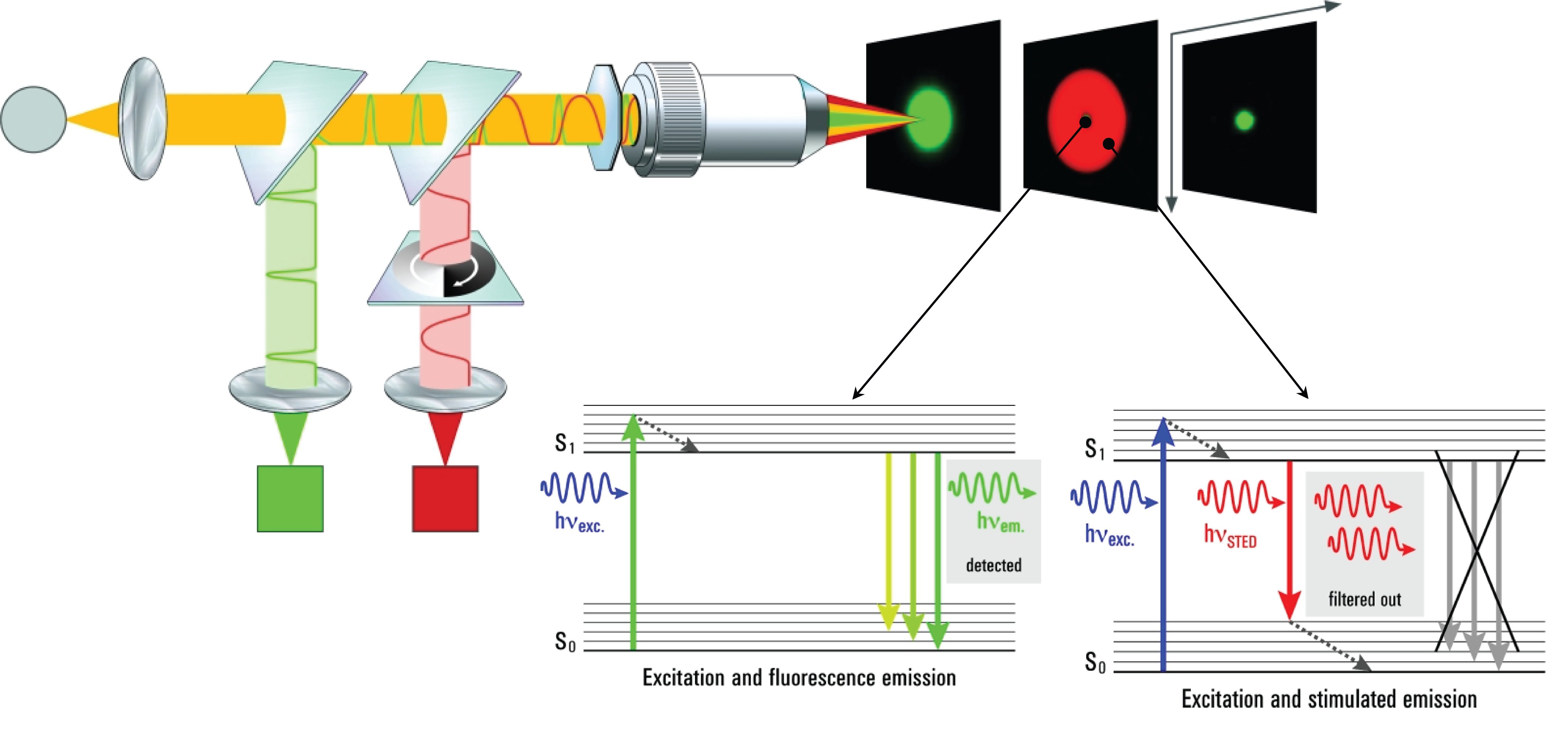
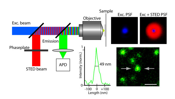
Traditional fluorescence microscopes are limited by the diffraction limitation of Abbe’s theory, and the resolution has never been able to break through <200nm. With the development of science, many scholars have proposed various methods and theories in recent years in an attempt to break through the Abbe diffraction limit. This laboratory adopts the STimulated Emission Depletion (STED) theory of Stefan Walter Hell, who won the Nobel Prize in 2014. Under good conditions, the resolution can theoretically be successfully increased to <50nm.
The core concept of STED technology is: assuming that the focus of one light can never break through the diffraction limit, then two different lights are used to interact with fluorescent signs to achieve the goal of ultra-high resolution. Among these two lights, one is used to excite fluorescent molecules (excitation light), which is focused in the usual way, and the other is focused into a donut pattern (depietion light), which is used to suppress all molecules except the center of the donut. All excited fluorescent molecules emit light.
When the hole in the center of the donut pattern is smaller than the diffraction limit, that is to say, only fluorescent molecules smaller than the diffraction limit can emit light normally, the image it presents will exceed the image resolution of the diffraction limit.
Related videos on the STED principle:
1 STED Confocal Super-Resolution - Leica TCS SP8 STED 3
2 Microscopy: Super-Resolution: Overview and Stimulated Emission Depletion (STED) (Stefan Hell)
STED can improve the resolution, and the cooperation of various environments is very important. If you want to use it, please be sure to follow the following items to achieve the best results:
1 Try to use STED special dye and use STED depletion laser 775nm wavelength
There are STED special dyes available on the market, please refer to: abberior, SPIROCHROME
If you really can't cooperate, you can also follow general fluorescent staining: staining protocol and antibodies recommended by the original manufacturer
2. Try to dye the fluorescence signal as strongly as possible: Since STED requires one more depletion laser to scan the sample, it is easier to bleach.
3. Please use #1.5H for coverslips. There are trial samples available in our core laboratory. You are welcome to request them.
4. For sealing glue, please use Mowiol, Glycerol, ProLongGold/Dimond, 86% glycerol + 4% NPG (N-propyl-gallate), 86% glycerol + 2.5% DABCO. Avoid the following mounting gels: Vectashield (Vectorlabs), Slowfade (invitrogen), Para-phenylenediamine (PPD)
Reference:
1 Introduction to the Technology and Application of Leica Laser Scanning Conjugate Focus Microscope, compiled by the Conjugate Focus Group of Meijia Instrument Co., Ltd., August 2000.
2 Stefan Hell, Wikipedia, January 14, 2021.
3 Instruments and Charges - Super-resolution Fluorescence Microscope Leica TCS SP8
4 3D STED (Stimulated Emission Depletion) Microscopy, Leica microsystems, January 25, 2021.
5 Hans Blom, Daniel Ronnlund, Lena Scott, Zuzana Spicarova, Jerker Widengren, Alexander Bondar, Anita Aperia, Hjalmar Brismar. Spatial distribution of Na+-K+-ATPase in dendritic spines dissected by nanoscale superresolution STED microscopy. BMC Neuroscience 2011, 12:16


